Detecting the Toy Car with OpenCV

OpenCV is a wonderful library with a lot of options on image processing. The simplest way to detect an object is by color. Color range can be in RGB/HSV/YUV. Algorithms for filtering work well with HSV.


  1. Find lower and upper ranges of HSV values
  2. Filter using color and find mask-color
  3. Optional: Filter using backgroundSubtractorMog2-> mask object movement AND both the masks
  4. Use erode, dilate and threshold to remove any noise
  5. Find contours. Assume that whatever contour we have are part of moving car, combine all points
  6. Find Centre of mass using moments
 Here is the sample code for finding the HSV Ranges from an image

void readPixels(final Mat imageHSV) {
        for (int i = 0; i < imageHSV.rows(); i++)
            for (int j = 0; j < imageHSV.cols(); j++) {
                double pixel[] = imageHSV.get(i, j);

                for (int k = 0; k < pixel.length; k++)
                    System.out.print(pixel[k] + "\t");
                System.out.println();
            }
    }

I have used GIMP to extract the car
This is converted to HSV and output from readPixels were copied to OpenOffice Calc (excel) to get the value ranges

final Scalar carColorThresholdHSVLow = new Scalar(90, 20, 180);
final Scalar carColorThresholdHSVHigh = new Scalar(102, 115, 255);


The output from Detection.

Source can be found here.

Back to the toy car: My experiments with Raspberry PI

What can I do with Raspberry PI?

It is a B+ model. To use it as a fan-less credit-card computer and do browsing? Nah.. it sucks. Too slow to respond. To connect to TV and make it "smart"?
Oh wow... Well, within a week of getting one; I have configured it to run Raspbmc (now KODI). It happily stated serving as my media manager.

I thought about the experiment I did for the OpenHouse event. Though it was done in two days (and nights), demonstrating a simple concept of tracking, it became one of the best post in terms of web traffic. So, I thought; why not try it again. So, I went and bought Remote Control Car (8$ around) from a local shop. Not to fry my RPI GPIO, I found a motor driver from FabToLab. Last weekend, I could finish the first set of code to control the GPIO and in the first run itself, worked as expected.

Dissection

  1. Opened up the remote (instead of car in the previous experiment)
  2. Removed the 4 Push Buttons underneath the joystick and soldered 4 Pins which were connected to RPI through the motor driver. Thanks to Jeshwanth for doing it for me.
  3. Used rpi 3.3V GPIO to power up the Remote. 

Coding

  1. Python GPIO Library to test the set-up. Left, Right and Accelerate were working
  2. Got back to my comfort zone language, Java with Pi4J
  3. Wrote the first set of code with "event loop". The events are the buttons and the joystick action is the duration of each event.

Code design: Thanks to Uncle Bob's talks

  1. Single Responsibility Principle and Separation of concerns
  2. Factory Pattern+ Singleton
  3. Program to Interface, prefer containment to derivation
  4. Use main program to "assemble" the pieces

High Level Design

  1. Interface: Drive
    •  drive (Activate forward/left/right)
    • release (turn off the pins which were kept on)
  2. DriveEvent (Drive,duration)
  3. Interface: AbstractDriveEventLoop
    • addEvent(DriveEvent)
    • fireEvent 

Implementation

  1. DriveLeft, DriveRight, DriveStraight, NoDrive,StopCar implementing Drive
  2. DriveFactory : Which generates the drives
  3. DriveEventLoop using  BlockingQueue.
  4. ReadInstructions which can take a BufferedReader and fill the event loop

Pictures and Result


 Interested to peek in to the code?

 Next steps

  1. Add a close loop control system with OpenCV
  2.  Add unit testing code (yeah yeah!!!, I know, I am yet to reach the TDD level)

The lambda calculus and nirvana

It is pretty interesting to see things evolve in time. Especially in Computer Science, where people have a (mis)-concept that everything here has a short "half-life".
I really did not believe so. I actually loved the "Science" part of Computer Science as much as I love the "engineering" part of it.

I do not know why and how did I miss such a wonderful thing as pure programming language (even if it may be just another jargon) and the relation to the term Lambda Calculus.  I did not come across even once in my entire 3 years time at IIT Madras. May be I heard, but did not listen.

Better late than never. Let me start with a slide from ACM SIGPLAN conference's talk on history of Haskell.
Screenshot from talk (copyright to ACM)
As said by Uncle Bob, "A paradigm takes away something. Functional programming paradigm took away the assignment statement"

A quick list of related things as I see it now
  • Moore's law stopped working
  • Multi-core chips evolved and became stable
  • The "useful" languages have "side effects" 
  • Principles of "REST" tells be stateless, so that it is cache-able,predictable and reproducible (sounds like a part of lambda effect) 
  • Single Responsibility Principle says it is a good practice to do one thing in one class. (Does it sound again like "one function" for one class?). 
  • Immutable variables ( the finals in java) is better for "thread" safety.

It is rather funny to see Java 8 came out with Lambda moving towards the "nirvana" after seven years from this talk.
Some of the links which inspired me

Presentation Slides

I felt, there may be people who may be interested in the summary of work our Team has done at IIT Madras on Wireless Sensor Network Testbeds (for monitoring applications and for target tracking)

  1. Testbed Design: From COTS to Open Hardware (SRM: 2012)
  2. NCC 2012 : Testbed Based Throughput Analysis in a Wireless Sensor Network
  3. IFIP Wireless Days 2011: A Testbed for Distributed Target Tracking
    with Directional Sensors
  4. IEEE LCN 2010: Capacity Analysis of Multi-Hop Wireless Sensor Networks using Multiple Transmission Channels

(This page will remain under construction always)

Omnet++ Lessons Part One

Omnet++ is one simulator which I liked a lot. It gave me enough confidence that I can build a network from scratch (like Steven's book building a complete TCP/IP stack). These files were written while I was at IIT Madras and reproduced here for learning purpose.
In this post, I start with a packet generator which simply generate a packet per given period of time.
This will introduce minimum number of files needed to write an Omnet application (cc c++ source file, the network descriptor : ned and the launcher : omnetpp.ini)


Tool: Omnetpp 4.xx (which is built over eclipse)

Not too much speech, let's get our hands dirty.


Periodic packet generator
input : number of packets to generate

Steps: Define a cpp file generator.cc


#include <omnetpp.h>
class generator : public cSimpleModule
{
private:
int nbPackets, packetCount;
cMessage*generateMsg;
protected:
virtual void initialize()
{
nbPackets=par("totalPackets");
packetCount=0;
generateMsg=new cMessage("selfMsg");
scheduleAt(simTime()+1,generateMsg);
}
virtual void handleMessage(cMessage *msg)
{
EV<<"generated the msg"<packetCount++;
if(packetCount<nbpackets)
scheduleAt(simTime()+1,generateMsg);
}
virtual void finish()
{
if (generateMsg!=NULL)
delete generateMsg;
}
};
Define_Module(generator);

The last line instructs the omnet tool to use this source as "generator"

Now let's build the network

generator.ned

package1;
simple generator
{
parameters:
int totalPackets = default(100);
@display("i=msg/job");
}
network one
{
submodules:
gen:generator;
}

Now let's write the launcher file: omnetpp.ini
network = one
**.gen.totalPackets = 10

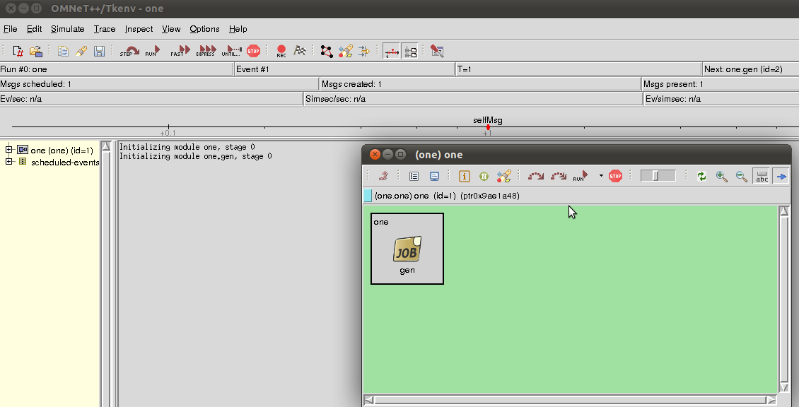
Build and run
Just right click "one" project and from build menu, build it.

Right click on omnetpp.ini and run the same.

Output is shown below.

Gentle introduction to research

About three and a half years back, when I was joining MS by research in IIT Madras, I did not have much idea about how to do it or what to look for or what could be the outcome. This blog is about the methods I learned over the years from my guides and colleagues on research. Please note that it is for people who are just starting research or thinking of doing research. Before I begin, a special thanks to the persons who inspired me (in the order in which I met them): Dr. Achutshankar S Nair (Director Centre for Bioinformatics, Kerala University- 2005) , Prof. PanduRangan (Faculty at IIT Madras -2006), Microsoft Research team (2006 and 2009), Dr. Shalu MA (Faculty, IIIT D&M Kanchipuram 2007) and Prof. Krishna Sivalingam (My guide at IIT Madras-2007) to put me in this track.

Research needs many things. First three are patience, patience and patience. Then a passion to make things work. If you believe you have both, then comes resources, guide and affiliation. If you think that research field is completely ethical, please re-think. In academia, it is "publish or perish" attitude for 99% of the researchers. So, let's get started.

1. Area of research
No matter what area you select, it is your passion for it which matters. Sometimes you have the freedom to select. But I have seen cases where the selection made a complete mess and people later cries for changing the area. In research, all areas are equally good (equally worse). You can not judge which one is good even your likes some areas. So, number one is passion.

I was passionate about cryptography and security. But I chose/was asked to work in low power wireless networks (wireless sensor networks). My passion for networking was the only thing I had while choosing this area.

2. Basics/Fundamentals
Though area selection may not be accurate to what you may like, the fundamentals of that area remains the same.
Main things you should try to know are
  1. The way an experiment has to be conducted
  2. Basic principles by which that area itself exists
  3. Works of core people in that area
  4. basics behind the real life solutions came from that area
You may use google effectively to find out these things.

I wanted to study wireless networks fundamentals. The general queries I used to search are
  • Handout wireless networks filetype:pdf. This will give a list of universities who runs courses in this subject. I visit their site, from the pdf links and try to see the references used, the tools (software programs, simulators) or the lab experiments designed for that course. I also tried to answer the homework questions and exam papers. Other materials like presentation slides, video lectures were also used to get a start.
  • Youtube Edu(www.youtube.com/education) is a great resource for video lectures in given area. Watch the classes by the best professors in the world. You will start enjoying the subjects.
3. Resources
Having done the background study, you should be familiar with the tools and experiments and should have done basic experiments in the tools/labs
You need to have
  1. Knowledge in using the tools (eg: Matlab or Simulators)
  2. Understand the limitations of the tools compared to real life scenarios. That is in which all cases the tool can fail.
  3. Access to recent literature on the area such as scientific journals, edited books on research, conferences proceedings. Don't worry there is google scholar (scholar.google.com) which can give you good results. Use British Library membership, if you don't have access to the journals/publications
  4. Guide and affiliation. See your guide as another human being. He may be wrong/ busy not looking what you are doing/ ignore the work you feel very important. It is you who is doing research and he/she is only a guide. He/she should only show the way and help you to walk your way. Affiliation is very important in later part of your research, if you do not wish to struggle a lot to get recognition of your work.

Selecting an institution and guide may not be in your hand. But try to be a part of the best. When I say best, it does not come cheap. You need to work really hard to keep the standards.

4. Literature survey


This is the situation where you have a guide, area of research and you are familiar with experiments and tools. Most of the cases, the publish or perish people might have put so much of mathematical jargon making it difficult for you to read or understand it. The method I tried was to
  1. Search for survey/ tutorials published in past two years. Each section of these articles describes current limitations and suggests possible improvements. Note down that.
  2. If possible try to repeat the experiments and verify the results. It gives different insights to the problem
  3. Do a forward search on the article you are reading to find out who else worked and improved/criticized the work you are reading. Again google scholar gives "cited by" which is highly useful.
  4. Do a reverse search on a very interesting article to see the basic papers the authors have used, to build the paper.
  5. Try to write to people who are currently working in this area for your basic doubts. At least 1 out of 10 will reply.
I might have read hundreds of articles in first six months, noting down the assumptions, making forward and reverse search and trying to just understand the results of a few classic papers in wireless networking. This part is not easy. But it helps a lot, while you write your own paper.

5. Pushing the boundaries
Once you are familiar with the classic papers in the area you are working and current open problems,
  • Try to do more experiments
  • Try different set of tools (different algorithms, approaches, assumptions)
  • Check if your assumptions holds good
  • Do come up with your own set of experiments, validate the input and expected output. Discuss with your guide/study group on the methods. At any time you can expect a blow to your assumptions or experiments
6. Publishing what you believe
Writing is the worst part in research. It is very difficult to select what is important. The things you feel important may not be that important to the people who read it. A well written paper might have undergone more than 20 iterations.
First time when you are writing a paper
  1. Write the literature survey and background section. This should make the reader ready for understanding your methodology and why it is different from existing work(s). Always try to include one or two diagrams describing the existing system and methodology
  2. Clearly state what is different in your work. It may be a specific case, but make sure that your background section is sufficient for a reader to understand what you are telling
  3. Not all things are to be explained to the ground level. Use citations to give reference to surveys, tutorials and basic articles you followed to write the paper
  4. Explain the different approaches in literature and what approach you are choosing. Justify them
  5. Write your assumptions and proposed solution
  6. Explain the experiment set-up with block diagrams/figures
  7. Add results, graphs and write clear explanations for whatever figure you add
  8. Add abstract, introduction and conclusion sections
  9. Give it for peer review and correct spelling and grammar
  10. Re-write and repeat step 9.
  11. Once you are ready, look for conferences and journals in your area.

For conference or journal call for papers, one tool I use is WikiCFP (http://www.wikicfp.com/cfp/). I have subscribed to other mailing lists which gives updates about call for papers in my area of research.

Survival Guide
I should say that, this can be really frustrating. .
  1. Have a good healthy routine.
  2. Do other activities daily, like playing
  3. Read articles from other areas
  4. Have open discussions with people working in different areas. You never know from where the spark can come.
  5. Present the summary of what you read/what you are working on at least once in two weeks. It keeps you in track, even if you feel you are lost.

Try reading articles by Douglas Comer (http://www.cs.purdue.edu/people/comer) and phdcomics (http://www.phdcomics.com/)


All the best!!!

Rethinking the assumptions about sensor model in WSN literature

This is an extract from the first draft of the thesis I am working on.
Please read it if you are sincerely working in Wireless Sensor Networks.

Oxford English dictionary defines sensor as ”a device which detects or measures a physical property and records, indicates, or otherwise responds to it”. A better definition from Wikipedia is ”a device that measures a physical quantity and converts it into a signal which can be read by an observer or by an instrument”. From the thermometers, barometers to microphone and cameras works with this principle making it integral part of our daily lives. A taxonomy of sensors can be drawn in the way in which it works such as (i) Active/Passive, (ii) Electrical/Mechanical/Electromechanical (iii)Proximity (How close the sensor has to be from the phenomenon).

The sensors in WSN research considers those which can produce electrical/digital information for a phenomenon of interest. Monitoring applications developed so far works in very close proximity of the phenomenon which will be a few centimetres (A structure health monitoring system or a patient monitoring system). On the other hand, a tracking system based on WSN prefers a sensor which has a better range (a few meters at least). Thus they sense energy emitted by the target (which is an energy propagation) unless it is a gas sensor or a chemical sensors which detects existence of a particle using chemical/biological properties. The problem of target tracking for surveillance mainly focuses on energy propagated from a target (source) which can be detected by using a sensors.

A distributed version of this concept employing inexpensive sensors with a low power wireless network for data collection created the field of target tracking using Wireless Sensor Networks. Despite the talks for years with hundreds of publications in this topic, hardly a few implementations came out. No reports exists on systems in large scale, which existed outside the research labs.

A closer look in to the main assumptions on the sensor part in target tracking reveals that they are not well formed. An analysis over the current assumptions has been done. The papers listed for analysis are mainly from journal articles with high impact factor or articles with a good number of citations.

R is the deterministic sensing range and R’ is the probabilistic sensing range. The area between R and R’ is the probabilistic range area where detection probability is assumed to be inversely proportional to distance
from R towards R’. Beyond R’ the sensing probability is assumed to be zero

Assumptions from literature

• It is assumed that all the sensor nodes have the same sensing range r and uncertainty sensing range r’

(r’≤1)[1]

• For simplicity, we assume that the sensing ranges of the sensors completely cover the region of interest with no overlap. In other words, the region can be divided into cells with each cell corresponding to the sensing range of a particular sensor [2]

• We assume the sensing range of a sensor is a disk with the sensor at the center. In this paper, we use homogeneous sensors, and hence all the sensors have the same sensing radius. Realizing that in real applications sensors may generate faulty readings due to measurement errors, we employ a practical sensing model .Sensors are assumed to correctly detect the presence and absence of targets within the inner disk Ac of radius Rc ; we call Rc as the reliable sensing radius. Otherwise, sensors can correctly detect the presence or absence of targets with only some nonzero probability when targets are present within disk Au of radius Ru but outside of Ac ,and Ru ≤ Rc [3].

• We assume binary sensing with a sensing range of Ri for a sensor Si , i.e., the footprint of sensor Si is a circle of radius Ri centered at Si inside which it can sense and outside of which it cannot sense[4].

• The sensing area of every node is assumed to be circular. Every node has the same sensing range (Rs) and communication range (Rc). The communication range is greater than two times that of the same sensing range. This is a sufficient condition for coverage to imply connectivity [5]

• For simplicity, we assume that each sensor has a circular sensing region of radius R: a sensor outputs a 1 if a target falls within the sensing disk of radius R centered at its loca- tion. The parameter R is termed the sensing range. However,our framework also applies to sensing regions of more complex shapes that could vary across sensors. We assume noise- less sensing for the time being: the sensor output is always 1 if a target is within its sensing range, and always 0 if there is no target within its sensing range, with 100% accuracy [6]

• With the model, a sensor with a nominal sensing range R can always detect a target’s presence if it is within R Re range from the sensor. No signal from beyond distance R is ever detected. And, the detection probability drops off continuously as the distance increases between R Re and R[7].


The fundamentals of sensing

Passive sensors watches the environment and generates an electric signal corresponding to the received energy. Examples of such sensors are passive infra-red and acoustic. Without much signal processing, these passive sensors will produce only intensity levels. The assumption of ”deterministic” circular range R will not be valid in any of these sensors simply because of the fact that it fully depends on the emitting energy at the source. Things become worse when there are obstacles in between which can absorb or change the energy. R thus becomes variable depending on emissivity of the source.

The active sensors generates the energy and measures the change in the energy reflected by the target. Using active sensors creates deterministic ranges, but it either has to be deployed in non-overlapped covering range or has to be enabled and disabled using a TDMA schedule. The disadvantage of using active sensors is that the presence of such a sensor can be detected as well as jammed easily. Another factor to be considered is that it consumes more energy than a passive sensor. This invalidate the theory that sensing range is a constant and a sensor reports correct values inside the sensing range.


Another assumption on boolean sensors, which produce 1 bit,thus reduce the overhead also does not hold especially in near real time target tracking scenario. The simple micro-controllers in motes uses 10-16 bit ADC which produces 2 bytes data per measurement. 1 Bit information has to be sent over wireless with a minimum protocol overhead of 19 bytes which hardly makes any difference in sending more accurate 2 byte data.


[1] X. Wang, J. Ma, S. Wang, and D. Bi, “Distributed energy optimization for target tracking in wireless sensor networks,” IEEE Transactions on Mobile Computing, vol. 9, pp. 73–86, 2010.

[2] J. Fuemmeler and V. Veeravalli, “Energy efficient multi-object tracking in sensor networks,” Signal Processing, IEEE Transactions on, vol. 58, no. 7, pp. 3742 –3750, 2010.

[3] D. Cao, B. Jin, S. K. Das, and J. Cao, “On collaborative tracking of a target group using binary proximity sensors,” Journal of Parallel and Distributed Computing, vol. 70, no. 8, pp. 825 – 838, 2010.

[4] P. Manohar and D. Manjunath, “On the coverage process of a moving point target in a non-uniform dynamic sensor field,” Selected Areas in Communications, IEEE Journal on, vol. 27, no. 7, pp. 1245 –1255, 2009.

[5] J.-P. Sheu and H.-F. Lin, “Probabilistic coverage preserving protocol with energy efficiency in wireless sensor networks,” in Wireless Communications and Networking Conference, 2007.WCNC 2007. IEEE, pp. 2631 –2636, 2007.

[6] N. Shrivastava, R. M. U. Madhow, and S. Suri, “Target tracking with binary proximity sensors: fundamental limits, minimal descriptions, and algorithms,” in Proceedings of the 4th international conference on Embedded networked sensor systems, SenSys ’06, (New York, NY, USA), pp. 251–264, ACM, 2006.

[7] W. Kim, K. Mechitov, J.-Y. Choi, and S. Ham, “On target tracking with binary proximity sensors,” in Proceedings of the 4th international symposium on Information processing in sensor networks, IPSN ’05, (Piscataway, NJ, USA), IEEE Press, 2005.

File Transfer (peer to peer) using two motes

After receiving requests from so many people, I thought of writing this simple application which can transfer file between two computers

Assumptions:
  1. Environment used is: TinyOS 2.1.0 with Ubuntu
  2. Knowledge to compile "BaseStation" application (coming with TinyOS) with a modification in Makefile : CFLAGS += - TOSH_DATA_LENGTH
  3. Basic understanding of file operations in Java
  4. No other nodes are in the vicinity which are transmitting data at that time
  5. Run SerialForwarder with Java applications in TinyOS
  6. Transfer is only for "text files"
If not, please refer my previous posts on these topics or read from tinyos wiki/documentation

Steps:
General
  1. Download the code from here
  2. Install BaseStation in two motes
  3. Put one mote in computer 1 and other in computer 2.
  4. Run the SerialForwarder

Sender /Receiver
  1. ECopy the FileSender folder
  2. Open a shell, navigate to this above folder
  3. Type in CLASSPATH=/opt/tinyos-2.1.0/support/sdk/java/tinyos.jar:.
  4. Type in make
  5. Type in java FileSender
  6. Repeat the same with Receiver
  7. Enter the file name with absolute path and extension at sender side
  8. Wait for the message "File ended"
That is all folks :-)

PS:
  1. Please come up with a reliable file transfer (like ftp)
  2. Please fix this code for any (byte) file instead of text files
  3. If you do any/both, please upload and post the link here

ZigBee/802.15.4 Sniffer

This is a simple ZigBee sniffer application which can dump raw data from any zigbee transmitter in 2.4 GHz and will work in the default channel set while compiling. The purpose is to demonstrate how to use sniffers.

Platform tested
MicaZ and TelosB ( Should work with Imote also)
Interfaces needed
Boot : To boot up the device
Leds : To indicate data capture
Receive : To capture the packet (provided by CC2420ReceiveC)
SplitControl : To control the radio
CC2420PacketBody : For reading the packet header
To run the program, assuming that you are using telosb , type in the shell/command prompt
java net.tinyos.tools.PrintfClient -comm serial@/dev/ttyUSB0:telosb


SniffC.nc
----------------
#include "printf.h"
module SniffC
{
uses
{
interface Boot;
interface Leds;
interface Receive as Rx;
interface SplitControl as RadioControl;
interface CC2420PacketBody as CPacketBody;
}
}
implementation
{
event void Boot.booted()
{
call RadioControl.start();
}
event void RadioControl.startDone(error_t err)
{
}
event void RadioControl.stopDone(error_t err)
{
}
event message_t* Rx.receive(message_t*msg,void*payload,uint8_t len)
{
uint8_t i;
cc2420_header_t *h=call CPacketBody.getHeader(msg);
for(i=0;ilength;i++)
printf("%u",msg->data[i]);
printf("\n");
printfflush();
call Leds.led1Toggle();
return msg;
}
}


SniffAppC.nc
------------------
configuration SniffAppC
{
}
implementation
{
components CC2420ReceiveC as CCC, LedsC, MainC, SniffC, CC2420CsmaC as CCS,CC2420PacketC as CCP;
SniffC.Boot->MainC;
SniffC.Leds->LedsC;
SniffC.Rx->CCC;
SniffC.CPacketBody->CCP;
SniffC.RadioControl-> CCS;
}


Makefile
COMPONENT=SniffAppC
CFLAGS+= -I$(TOSDIR)/lib/printf
CFLAGS += -DCC2420_NO_ACKNOWLEDGEMENTS
CFLAGS += -DCC2420_NO_ADDRESS_RECOGNITION
CFLAGS += -DENABLE_SPI0_DMA
include $(MAKERULES)

Debugging NesC made easy with Printf library


Put watch , breakpoints ... all sort of such powerful debugging we miss when we do tinyos and nesc. I had a good struggle to find out what went wrong in a code till I figured out serialforwarder and the libraries to print values in between. This again needs many routine calls and stuffs.
To make things easier, there is a library "tinyos printf". Anyone who had used printf in C, same syntax will work. This post is on how to use tinyos printf library.
Before we begin, I assume that you are familiar with serialforwarder interface and simple blink application. Again the screenshots are done with original mote. Avrora users can do the same with micaz compilation, then follow the post using serialforwarder interface with avrora.

This is simple application which generates random numbers with Random interface and prints the value to the screen. All you need is
  1. Include printf path in Makefile
  2. Include printf.h in your application
  3. Invoke the Serialforwarder
  4. Type java net.tinyos.tools.PrintfClient and see the output.
The screenshots are given below.

The corresponding files can be found here

Related posts
Running tinyos programs using avrora
Using Serialforwarder with Avrora

Simple One Dimensional Routing in TinyOS 2.x /2.10

Program listing: Routing in one dimension
OS: TinyOS 2.10/ TinyOS 2.x
Tools used : none
Assumptions: You are able to understand BlinkToRadio example from Tinyos tutorials.
Concept used: TX_POWER is set when sending a data to do multiple node transmission in a small room testbed. ( If you want to use it, you need to include the following in the AppC
components CC2420PacketC;
App.CC2420Packet->CC2420PacketC;
)

When a packet is received, it check for the target. If target is not current node, it compares its own id with target. Nexthop id is chosen accordingly.

Running the program:
1)Modify the BlinkToRadio application in receiving packets and include the routing decision.
2) Write a test program. Fuse it to say nodeid 10. Try to send data to 14 and 3. For 14 it should hop right. For 3 it should hop left.


void sendMessage(uint8_t data, uint16_t nodeid)
{

if (!busy) {
BlinkToRadioMsg* btrpkt =
(BlinkToRadioMsg*)(call Packet.getPayload(&pkt, sizeof(BlinkToRadioMsg)));
if (btrpkt == NULL)
{
return;
}
btrpkt->nodeid = nodeid;
btrpkt->counter = data;
call CC2420Packet.setPower(&pkt,MY_TX_POWER);
//routing decision
if(nodeid
{
//send left
if (call AMSend.send(TOS_NODE_ID-1,
&pkt, sizeof(BlinkToRadioMsg)) == SUCCESS)
{
busy = TRUE;
}
}
else

{
//send right
if (call AMSend.send(TOS_NODE_ID+1,
&pkt, sizeof(BlinkToRadioMsg)) == SUCCESS)
{
busy = TRUE;
}
}
}
}


// The Header file is modified to get desired output
//Transmission power is set to two. This will help to run the program in actual mote with multiple hops in a small room.

#ifndef BLINKTORADIO_H
#define BLINKTORADIO_H

enum {
AM_BLINKTORADIO = 6,
TIMER_PERIOD_MILLI = 250,
MY_TX_POWER=1
};

typedef nx_struct BlinkToRadioMsg {
nx_uint16_t nodeid;
nx_uint16_t counter;
} BlinkToRadioMsg;

#endif

If you could implement this, try to do it for 2 dimension.

Hands on experiments with micaz, MTS310 and MIB520

This post is after the first set of trials with micaz mote. Till now worked only with telosb, which has usb interface and programming in single board including sensors on board.
This experiment is not conducted in avrora or any emulator.

Mote used- Micaz- CC2420 Radio (Zig-Bee compliant) : The range was much better than Telosb. It gave 21metres compared to 8 metres in telosb.
Following image shows Micaz mounted with MTS310 sensor board

Sensor Board- MTS310 ( light, temp, acoustic,acoustic actuator, seismic, magnetometer sensors)

Programming board- MIB520CB USB/JTAG

The first program came to my mind was to make buzzer on. After searching for the platform files, in mts300 board folder (/opt/tinyos-2.1.0/tos/sensorboards) I found Sounder file.
The application I wrote has 2 files BuzzerC and BuzzerP
BuzzerC
configuration BuzzerC {
}
implementation {
components MainC, BuzzerP, LedsC,SounderC ,new TimerMilliC() as MyTimer;;

MainC.Boot <- BuzzerP;
BuzzerP.Mts300Sounder -> SounderC;
BuzzerP.Leds -> LedsC;
BuzzerP.Beep -> MyTimer;
}

BuzzerP
module BuzzerP
{
uses
{
interface Boot;
interface Mts300Sounder;
interface Timer as Beep;
interface Leds;
}
}
implementation
{
uint8_t count=0;
event void Boot.booted()
{
call Beep.startPeriodic(500);

}
event void Beep.fired()
{

count++;

if((count==2))
{
call Leds.led0Toggle();
call Leds.led1Toggle();
call Leds.led2Toggle();
count=0;
call Mts300Sounder.beep(10);
}
}
}

The code is self explanatory....

Following was the error came while compiling
"Programmer is not responding"
This is because MIB520 has 2 usb ports. One used for programming and other for data.
The "motelist" command will not list any mote connected to MIB520. Instead you have to go to system log and check for the two usb ports activated after pluging in the board. Assuming that first one is usb0 and second one is usb1, the syntax for uploading a new program is "make micaz reinstall.2 mib510,/dev/ttyUSB0" where 2 is the node id

Now you can test the "Antitheft" application which worked fine after giving /dev/ttyUSB1:micaz for serialforwarder

Tracking Using RSSI: application in tinyos2.10+ubuntu+java

This small project was done as part of our OpenHouse event during Tech Fest Shaastra2008 atIIT Madras. It's the first application of its kind I have written.
Please read my previous posts to understand basics, if you are not familiar with basic terms

Project : Target tracking using RSSI with TelosB
Types of nodes: Mobile node, Static nodes and base station
Tools: Java serialforwarder and customized extension of listen class
Routing protocol used: Collection
Tracking scenario: 1 Dimensional

The details
Mobile node will send a blank packet with specific interval while moving. The static nodes will catch that signal and measure the RSSI value. It will be transmitted to BaseStation. Base station is the multihoposcilloscope base. The value received by base station node can be read using java serialforwarder and Listen class.
However the Listen class gives only raw information. So the program is modified and customized to get values. RSSI values are scaled to a positive value. Value we have got are between 0 and 89 using telosb motes.
The GUI is having 10 grids with 6 static nodes, but can scale to any number of nodes.

Code can be downloaded from here

Using SerialForwarder Interface of TinyOS with Avrora

Dear reader,
Special thanks for the feedback and comments. Please continue supporting this small effort of mine to tinyos community.
As I promised in last post, here is the first step to analyze the RSSI values from a mote. In order to understand concept of base station and how things are done in real world, the following tutorial may help you.
As usual, sample code is provided at the end

Assumptions:
1) You have done up to the previous post, radio communication using cthreads. If not, please have a look at it. We are using the same program here for further analysis with a base station.
2) The username is "test"
3) You have eclipse installed and running.
4) You know how to add CLASSPATH for custom jar library

Before we begin, a small note on base station. Base station in real time can be a sophisticated node with high transmission range or a normal mote connected to computer. In either way, it act as a sink for data collection. That means, every application you develop using WSN needs to run the base station.

With this, here we begin.
Part 1: Making program ready for SerialForwarder
  1. Copy the folder BaseStation from /opt/tinyos-2.1.0/apps to /home/test/Serial
  2. Take shell and navigate to ~/Serial
  3. Compile the program. "make mica2"
  4. Convert the main program to avrora compatible format convert-avrora build/mica2/main.exe base.od
  5. Move the base.od to parent folder. mv base.od ../
  6. Copy the sender.od from previous example to Serial folder
  7. Instead of our previous post step, command for avrora is different here. " avrora -simulation=sensor-network -seconds=160.0 -monitors=serial,real-time -platform=mica2 -nodecount=1,1 base.od sender.od"
  8. This will give a display "Waiting for serial connection on port 2390..."
If everything is fine, the O/P will be similar to the following


Part 2: Opening a new project in Eclipse and adding TinyOS library
  1. Open a new java project in Eclipse
  2. Copy the following code

Running Program
  1. Add java library path for suport for TinyOS serialforwarder
  2. Compile.
  3. Run the serialforwarder
  4. Modify the entry in serialforwarder to "network@localhost:2390"
  5. Start Server
  6. Now the counter will be running for "packets received"
  7. With out closing the serialforwarder, go back to eclipse and run the Listen
  8. Observe the output.

For those who are done with this.
Please have a look at Octopus project
If you are able to run the code from Octopus in avrora, it's a good sign!!!
Cheers

Download java code
Links you may be interested in
  1. Radio Communication using cthreads(tosthreads library)
  2. Running cthreads (tosthreads) program in Avrora
  3. BlinkToRadio in Avrora
  4. Running TinyOS programs using Avrora

Radio Communication Simplified Using TOSTHREADS

Dear reader,
Welcome back again with another post on tosthreads or cthreads in TinyOS. As usual my assumption is that you have followed up to my last post on cthreads. If not, it's beter to do it now before continuing!!!
If you have visited tinyos wiki, you may wonder how complex the radio communication code for BlinkToRadio. All that we are trying is to send a simple msg and it needs lot of files. Till now I have not seen a better way of doing that communication. (I am also learning things in NesC)
What we are trying to do is , to use 2 nodes "a sender and a receiver". Sender will send the data and receiver will receive it and blink the leds. We will write the program and will test it using Avrora as usual.

Algorithm Sender
  1. Initialise radio
  2. Create packet
  3. Set count
  4. Send the data
  5. Increment count and repeat 4
Here, we need to create a nx_struct as a wrapper. Those who tried to implement BlinkToRadio will see that this part is same
After that create a thread which will continuously send the data.
#include "tosthread.h"
#include "tosthread_amradio.h"
#include "tosthread_leds.h"
typedef nx_struct RadioMsg {
nx_uint8_t counter;
} RadioMsg;
//Initialize variables associated with each thread
tosthread_t radio_thread;
void radio_thread_foo(void* arg);
message_t send_msg;
RadioMsg* rdata; //pointer into message structure
//Initialize messages for sending out over the radio


void tosthread_main(void* arg)
{
while( amRadioStart() != SUCCESS ); //wait till radio is ready
tosthread_create(&radio_thread, radio_thread_foo, NULL, 200);
}
void radio_thread_foo(void* arg)
{
uint8_t count;
rdata=radioGetPayload(&send_msg, sizeof(RadioMsg));

for(;;)
{
count++;
rdata->counter=count;
if(amRadioSend(AM_BROADCAST_ADDR,&send_msg, sizeof(RadioMsg), 2) == SUCCESS)
{

setLeds(count);
tosthread_sleep(1000);
}

}
}

The code is self explanatory!!!!

Algorithm Receiver
  1. Initialise the radio
  2. Wait for a packet
  3. Get the data
  4. Blink LED s
#include "tosthread.h"
#include "tosthread_amradio.h"
#include "tosthread_leds.h"
typedef nx_struct RadioMsg {
nx_uint8_t counter;
} RadioMsg;
//Initialize variables associated with each thread
tosthread_t radio_thread;
void radio_thread_foo(void* arg);

//Initialize messages for sending out over the radio
message_t radiomsg;

void tosthread_main(void* arg)
{
while( amRadioStart() != SUCCESS ); //wait till radio is ready
tosthread_create(&radio_thread, radio_thread_foo, &radiomsg, 200);
}
void radio_thread_foo(void* arg)
{
message_t* m = (message_t*)arg;
RadioMsg *rm;
uint8_t count=0;
for(;;)
{
if((amRadioReceive(m, 50, 2))== SUCCESS)
{

// if(radioGetPayloadLength(m)==sizeof(RadioMsg))
{
rm=radioGetPayload(m,sizeof(RadioMsg));
setLeds(rm->counter);
tosthread_sleep(1000);

}
}
}
}


Create makefile for each and compile the code using "make mica2 cthreads"
Follow the steps in last post, you can run it using avrora.

Download Code

Links you may be interested in
  1. Working with serialforwarder in Avrora
  2. Running cthreads (tosthreads) program in Avrora
  3. BlinkToRadio in Avrora
  4. Running TinyOS programs using Avrora

Working with motes using TOSTHREADS... An easier way to do TinyOS programming

Dear reader,
Thanks a lot for responses and comments to make my small efforts on TinyOS programming a success. So here is another good news for C programmers who wants to work on TinyOS. No more NesC codes and hurdles of it.
TinyOS 2.10 comes with integrated library for tinythreads. The library examples can be found in "/opt/tinyos-2.1.0/apps/tosthreads" for a default installation.
The directory under it, "capps" is specially interesting to us.

Here I assume that you have done TinyOS installation and Avrora configuration from my past posts and enjoyed testing the blink application and blink2radio application.Also you have done programming in Threads using C.

What is so exciting in this folder? Well we are back to our favourite language "C". Let's rewrite the program using C and tosthreads

Quick refresh on Posix standard Thread in C

  • Declare thread_t instances
  • Define functions of void* foo(void*)
  • Create thread using pthread_create()
TOSTHREADS programming
Revisiting Blink

#include "tosthread.h"
#include "tosthread_leds.h"
tosthread_t blink;

void blink_thread(void* arg);
void tosthread_main(void*arg)

{

tosthread_create(&blink,blink_thread,NULL,400);
}
void blink_thread(void*arg)
{
uint8_t counter;
for(counter=0;counter<8;counter++)
{
setLeds(counter) ; tosthread_sleep(200);
}
}

Save the above code as Blink.c
Making the program : Makefile

TOSTHREAD_MAIN=Blink.c
include $(MAKERULES)
Save above code as Makefile

Compiling the program
Open a shell in the same folder where Makefile and Blink.c are stored. Type
make mica2 cthreads
If everything goes fine you will get output similar to


Running the program using Avrora
From shell change directory to "mica2/build"
cd mica2/build
Convert the main.exe to blink.od
convert-avrora main.exe blink.od
Run the simulation
avrora -platform=mica2 -seconds=3 blink.od
Output will be similar to the following


Tip: Modify the program to make the thread running for ever instead of 8 counts.
Keep reading!!!!
I will be back with more programs.
Meanwhile if you have any simple code, please send it or add as comments so that others will be benefited.

Links you might be interested

Running TinyOS Programs using Avrora

Running multiple node simulation using Avrora: Example BlinkToRadio


Installation of TinyOS 2.10 in Ubuntu

WSN: A layman's view

Running BlinkToRadio using Avrora

Dear reader,
So it's time to test something more interesting. Here I assume that you have already installed tinyos2.10 and Avrora using my previous posts and you have gone through the TinyOS wiki about BlinkToRadio. The tinyos install directory contains app/tutorials folder where you can find implemented code of all these programs.

I am not explaing the code, but just try to demonstrate how to run the code using Avrora

Step1
Build the program using "make mica2"

Step 2
Convert the main.exe file to radio.od
"convert-avrora main.exe radio.od"

Step 3
Run the program using sensor network mode of avrora
"avrora -simulation=sensor-network -seconds=2.0 -nodecount=2 radio.od"

If things work fine, output will be similar to the following


Play around with the avrora monitor options to see more options
Have fun!!!!!!

Running TinyOS programs using Avrora

Avrora
The readers may be wondering, the post for installation of TinyOS does not have TOSSIM installation steps. It's because I have found Avrora emulator more easier than TOSSIM scripts. Avrora is emulator/simulator for wireless sensor networks, written in Java by UCLA group. It takes an object dump of tinyos programs over AVR platforms ( mica2/micaz) and is capable of single node emulation for verification of the program as well as multiple node simulation. The gui provided with Avrora is not functional when this document is written.

Here I assume that username is "test", tinyos 2.10 and java run time environent are installed. The code used for illustration along with one more application is given for download at end of tutorial

Download the Avrora [Beta 1.7.105] from the site.

Setting up the environment
  1. Copy the avrora jar file in a directory say "home/test/avrora/avrora.jar"
  2. Download the converter.sh
  3. Extract the tar file and get the converter.sh
  4. Assuming that path for converter.sh is "home/test/avrora/converter.sh" copy the following code to ".bashrc"

  5. alias avrora='java -jar /home/test/avrora/avrora.jar'
    alias convert-avrora='sh /home/test/avrora/converter.sh'
  6. Close all the shells opened
  7. Take a new shell and type avrora /convert-avrora, it should produce the following output


Writing our first program: Blink
Please note that this is not blink program described in TinyOS wiki. This is much more simpler version of it.
This consist of following steps
  1. Interfaces : Boot, Leds
  2. Implementation file BlinkC
  3. Define Wiring
  4. BlinkC -> MainC.Boot
  5. BlinkC.Leds -> LedsC ( 3-5 steps is in BlinkAppC )
  6. Write the implementation file BlinkC.nc
  7. Write the Makefile
  8. Compiling
  9. Running the application using Avrora
Save all the following codes in "blink" folder ( say /home/test/tinyospgs/blink)

#include "Timer.h" module BlinkC { uses interface Leds; uses interface Boot; } implementation { event void Boot.booted() { call Leds.set(1) ; call Leds.set(2); call Leds.set(3); call Leds.set(4); call Leds.set(5); call Leds.set(6); call Leds.set(7); } }
Save the above code as "BlinkC.nc"
configuration BlinkAppC
{
}
implementation
{
components MainC, BlinkC, LedsC;
BlinkC -> MainC.Boot;
BlinkC.Leds -> LedsC;
}
Save above code as BlinkAppC.nc
COMPONENT=BlinkAppC
include $(MAKERULES)

Save above as Makefile

Now take a shell, navigate to this folder
Type "make mica2 "
If everything is correct, it will create build/mica2 folder
Navigate to mica2 folder in shell (cd build/mica2)
Type "convert-avrora main.exe blink.od"


Run the simulation by "avrora -seconds=5.0 -platform=mica2 blink.od"
Output will be similar to the following


Congratulations!!!!!!!
You are successfully emulated the first program
Note that only AVR platforms such as Mica2/Micaz is supported by Avrora

Links you might be interested in
Code Download this code and blink with timer here

Radio communication simulation simulation using Avrora

TinyOS programming using C an eazier way : tosthreads simulation using Avrora